STEM BOT Pro Kit Building Guide: How to Build the STEM BOT
The STEM BOT Pro Kit allows students to explore the possibilities of STEM and mobile robotics in various applications from basic to advanced concepts.
These build instructions will walk you through the steps of building the STEM BOT.
View as a PDF. View Parts List.
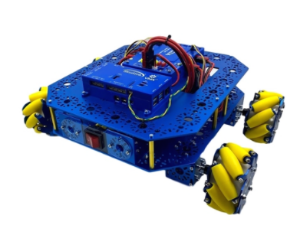
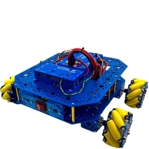
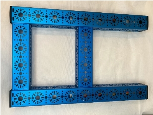
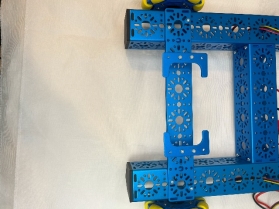
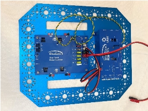
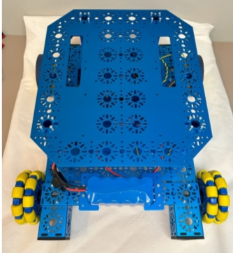
This is example of what the competed project will look like.
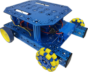
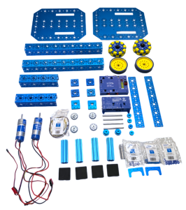
Table of Contents:
- STEM-BOT Build Instructions
- Frame Assembly
- Back Wheels Assembly
- Front Wheels & Battery Mount Assembly
- Base Plate & Electronics Assembly
- Wiring Guide
- Software Setup for Programming your robot
- Programming your STEM BOT
- Configuring the project for VMXpi
- Deploying Code
- Adding Vendor Libraries
- STEM BOT Parts List
- 3D CAD files for all parts are available at www.studica.com/studica-robotics-resources
- About the VMX Robotics Controller
- Helpful Resources: Example of Code used for VMX
- Troubleshooting for VMX: Updating Firmware
- VMX: Map of Ports and Inputs
- About the Titan Quad Motor Controller
- Titan: Map of Ports and Inputs
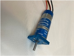
- About the Maverick DC Motors
STEM BOT Build Instructions:
This is a step-by-step guide for assembling the STEM-BOT along with an example of programming a two-wheel drive with the VMX. The example code is found here: https://github.com/studica/WorldSkills-Example-Projects/tree/main/TwoWheelDrive in both Java and C++. In Java it is contained in the src/main folder.
Frame Assembly:
Step 1: Attach the End Piece Plates to the ends of both 192mm U-Channels using the M3 x 10mm Button Head Cap Screws
Step 2: Attach the End Piece Plates of the 192mm U-Channels to the 432mm U-Channels using 4 M3 x 10mm Socket Head Cap Screws each.
Step 3: Place 4 Rubber U-Channel Bumpers to each end of the 432mm U-Channels
Step 4: Attach the Maverick DC Motor to the Motor Mount Plate using 6 M3 x 10mm Button Head Cap Screws:
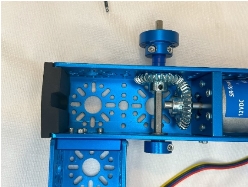
Step 5: Attach 1 30 Tooth Bevel Gear onto the shaft of the Maverick Motors (Do not tighten set screws)
Back Wheels Assembly:
Step 6: Attach the motors to the Frame by having the recess into 432mm U-Channels and using the M3 x 12mm Socket Head Cap Screws (Repeat for other side of frame).
Step 7: Place 14mm Bearings onto the 14mm hole patterns of the 432mm U-Channel that are perpendicular to the end of the Maverick Motor’s shaft (Repeat for other side of frame).
Step 8: Insert the 6mm x 96mm D-Shaft through the bearings as well as a 30 Tooth Bevel Gear. This gear as well as the gear mounted on the Maverick Motor shaft should both be positioned so that they mesh well with one another, once they do, tighten the gears to their shafts with their set screws.
Step 9: Attach a 6mm D-Shaft Collar Clamp on one end of the 6mm x 96mm D-Shaft with a 1mm Thick Shaft Spacer between the collar and bearing.
Step 10: Place two 5mm Thick Shaft Spacers then one Clamping Shaft Hub-v2 onto the 6mm x 96mm D-Shaft and secure the shaft hub using the set screws.
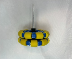
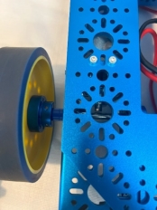
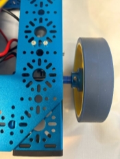
Step 11: Use 4 M3 x 12mm Socket Head Cap Screws to Attach the 100mm Drive Wheel to the Clamping Shaft Hub (repeat for other side of frame)
Front Wheels & Battery Mount Assembly:
Step 12: Stack two 288mm x 40mm Flat Brackets on top of one another and attach them to the frame using four M3 x 30mm Screws and four Kep Nuts on each side.
Step 13: Attach two 25mm Male to Female Standoffs to each Batter Clip with two M3 x 10mm Socket Head Cap Screws. Then secure the Battery Clips to the 288mm x 40mm Flat Brackets
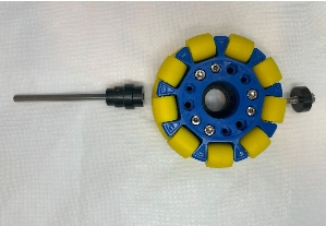
Step 14: The 100mm Omni Wheel comes with its own shaft hub. Attach a 6mm x 96mm D-Shaft into the shaft hub and tighten with the set screws. Once tightened, screw the Hub onto the Omni-Wheel (repeat for other side of frame)
Step 15: Place two 14mm OD Bearings onto each side of the hole patterns of the 432mm U-Channels (Repeat for other side of frame)
Step 16: Insert the Omni Wheel Shaft through the bearings with a 1mm Thick Shaft Spacer between the bearing and shaft hub. (Repeat for other side of frame)
Step 17: Attach a Collar Clamp to the opposite end of the D-Shaft with a 1mm Thick Spacer between the clamp and U-Channel and secure by tightening the set screw. (Repeat for other side of frame)
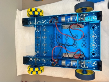
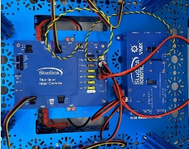
Base Plate & Electronics Assembly:
Step 18: Secure the Titan Quad Motor Controller to the Base Plate using 4 M3 x 30mm Socket Head Cap Screws and 4 M3 Kep Nuts”.
Step 19: Secure the VMX Robotics Controller to the Same Base Plate using 4 M3 x 30mm Socket Head Cap Screws and 4 M3 Kep Nuts
Important: Refer to the Wiring Guide on page 9 before completing assembly.
Step 20: Align the Base Plate with the VMX and Titan so that the Titan is towards the back of the robot frame and the hole pattern aligns with the back 192mm U-Channel and the 432mm U-Channels. When aligned properly, screw 2 M3 x 12mm through the base plate and robot frame to the Motor Mount Plate
Step 21: Attach the Base Plate to the frame of the robot by screwing 4 96mm T-Slot Extrusions to the frame and baseplate using 4 M3 x 12mm Socket Head Cap Screws for each extrusion. Then 2 M3 x 12mm Socket Head Cap Screws
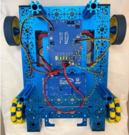
Step 22: Attach another Base Plate to the extrusions using four M3 x 12mm Socket Head Cap Screws
Wiring Guide
The Titan Wire Pack contains the required cables and wires to power the VMX and provide communication between the Titan and VMX. The two devices communicate with one another via CAN (Control-Area-Network) Bus Cable (Green Low, Yellow High)
Step 23: Connect the power cable to the power output port on the Titan to the power port of the VMX. This allows for the Titan to distribute power to the VMX.
Step 24: Connect the Powerpole 45 Extension cable to the power input port of the Titan.
Step 25: Connect the green cable to the Green (L) port of the Titan and L (GRN) port of the VMX and connect the yellow cable to the Yellow (H) port of the Titan and the H(YEL) port of the VMX.
Step 26: Connect the Left Motor and Encoder cables to the M0 port. Then connect the Right Motor cables and encoder cables to the M2 port.
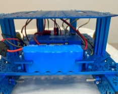
Step 27: Place the Battery in between the battery clips and connect it to the Powerpole 45 Extension Cable.
Software Setup for Programming your Robot
Installing WPILib & VS Code:
To install WPILib, access our international website here: https://www.studica.co/resources-4 and click on the “Download all the Studica Robotics Resources” link:
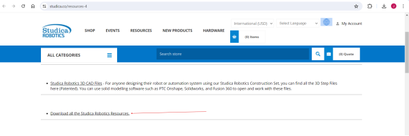
Find the appropriate operating system you are using (Windows, macOS, Linux) and install the zip files for VSCode and WPILib. The installation files can be alternatively found through the WorldSkills Technical Documentation & Software resources on Studica’s International website: https://www.studica.co/resources-4
For Windows 11: FRC Driver Station
For Windows 11 users, FRC Driver Station is the interface software used to access and communicate with the robot. To download, click here to access the FRC Game Tools components: https://www.ni.com/en/support/downloads/drivers/download.frc-game-tools.html#500107 and download the latest version.
Programming your STEM BOT
Configuring the project for VMXpi
The VMXpi Extension must be installed so the VMX can be the deployment target. In the extensions tab, click on the search bar and enter “VMX-pi”:
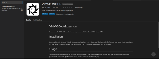
Install this extension and it should appear next to the WPILib logo.
Deploying Code:
To deploy your code to the VMX, click on the VMX-Pi logo:
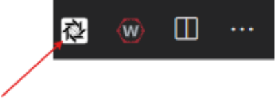
VMX-Pi logo
The following commands will pop up:
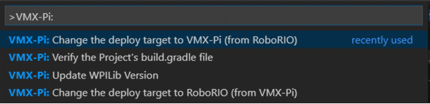
Clicking the “Change the deploy target to VMX-Pi (from RoboRio)” will update the build.grade file to update the target as the VMXpi and cache any missing libraries.
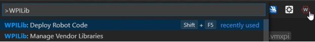 To deploy the code to the VMX, click on the WPILib Logo and click on the command “Deploy Robot Code”,
Adding Vendor Libraries
The vendor libraries supported on the VMXpi are below. To install these libraries on VS Code, open the command palette using Ctrl+Shift+P or F1. Type into the command palette “Manage Vendor Libraries”, Select Install new libraries(online), copy and paste the links into the command palette and press Enter.
NavX Library: https://dev.studica.com/releases/2023/NavX.json
Titan Library: http://dev.studica.com/releases/2020/Studica.json
STEM BOT Parts List
3D CAD files for all parts are available at www.studica.com/studica-robotics-resources
Name | Part # | Qty | Image |
Electronics & Accessories |
12V 3,000 mAh NiMH Battery Pack, PP45 | 70018 | 1 | 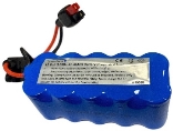
|
NiMH Battery Pack Charger – PP45 | 70019 | 1 | 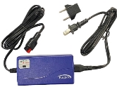
|
Titan Quad Motor Controller | 70152 | 1 | 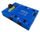
|
Titan Cable Pack | 70162 | 1 | 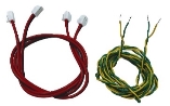
|
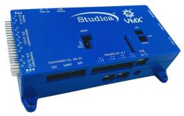
VMX Robotics Controller | 70176 | 1 | 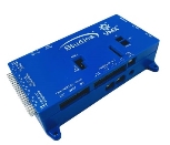
|
Maverick 12V DC Gear Motor w/Encoder | 75001 | 2 | 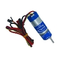
|
U-Channel |
432mm U-Channel | 76010 | 2 | 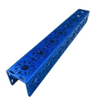
|
192mm U-Channel | 76015 | 2 | 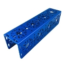
|
Flat Brackets |
288mm x 40mm Flat Bracket (2 pack) | 76061-2 | 1 | 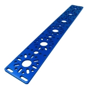
|
Robot Base Plate | 74001 | 2 | 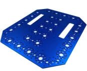
|
Extrusions |
96mm T-Slot Extrusion | 76127 | | 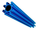
|
Irregular Brackets |
Battery Clip (2 pack) | 76088-2 | 1 | 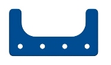
|
Mounting Plates |
Motor Mount Plate | 76140 | 2 | 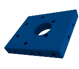
|
End Piece Plate (2 pack) | 76143-2 | 2 | 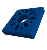
|
Axles |
6mm x 96mm D-Shaft | 76161-6 | 1 | 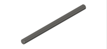
|
Standoffs |
25mm Male to Female Standoff | 76184-12 | 1 | 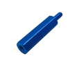
|
Screws and Nuts |
M3 x 10mm Socket Head Cap Screw | 76201-100 | 1 | 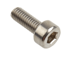
|
M3 x 12mm Socket Head Cap Screw | 76202-100 | 1 | 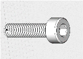
|
M3 x 10mm Button Head Cap Screw | 76203-50 | 1 | 
|
M3 x 30mm Socket Head Cap Screw | 76206-50 | 1 | 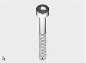
|
M3 Kep Nut (100 pack) | 76204-100 | 1 | 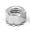
|
Gears |
30 Tooth Bevel Gear | 76219-2 | 2 | 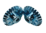
|
Wheels |
100mm Omni Wheel | 76260 | 2 | 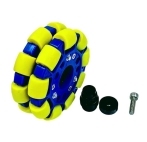
|
100mm Drive Wheel | 76262 | 2 | 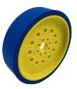
|
Bushings, Bearings, Collars, & Spacers |
Clamping Shaft Hub-v2 | 76280 | 4 | 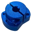
|
Collar Clamp | 76320 | 4 | 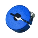
|
14mm Flange Bearing | 76302-12 | 1 | 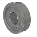
|
Shaft Spacer 1mm, Nylon (24 pack) | 76305-24 | 1 | 
|
Shaft Spacer 5mm, Nylon (12 pack) | 76307-12 | 1 | 
|
Rubber Grommet | 76504-10 | 1 | 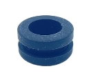
|
U-Channel Bumper (4 pack) | 76505-4 | 1 | 
|
| | | | | | | | | | | |
About the VMX Robotics Controller
As the “brain” of a robot, the VMX Robotics Controller is a powerful, versatile Linux-based robot controller that offers compatibility with programming languages including Java, C++, Python, and LabVIEW, along with support for ROS. Integrated with the NavX-IMU and combined with the Titan Quad Motor Controller, the VMX acts as the powerful “brain” of your robot. Capable of programming for both tele-operated and autonomous controls. It also houses an integrated NavX IMU (Inertial-Measurement-Unit) for advanced movement performance in tele-op and autonomous driving.
Helpful Resources: Example of Code used for the VMX
This guide will go over an example project from Studica Robotics github, using the VMX. The example code can be found here: https://github.com/studica, in the WorldSkills-Example-Projects repository under the Popular Repositories.
Troubleshooting for VMX: Updating Firmware
Certain cases may require the firmware to be updated for the VMX to improve functionality or fix any bugs. To do so, use the following instructions on our WorldSkills resources page: https://docs.wsr.studica.com/en/latest/docs/VMX/update.html
A firmware update should be performed in case there
VMX: Map of Ports and Inputs
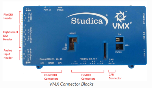
Connector Block | Connector Type | Location on VMX |
Flex DIO Header | 3-pin PWM-style | Left-side Top |
High Current DIO Header | 3-pin PWM-style | Left-side mid |
Analog Input Header | 3-pin PWM-style | Left-side bottom |
Comm DIO Connectors | 4-pin JST GH | Bottom-left |
Flex DIO Connectors | 4-pin JST GH | Bottom-middle |
CAN Connector | 2-wire Weidmuller | Bottom-right |
About Titan Quad Motor Controller:
The Titan Quad Motor Controller is a 4 channel CAN-based motor controller. Combined with the VMX, the Titan acts the Power Distribution Panel (PDP) for your robot, primarily for the VMX.
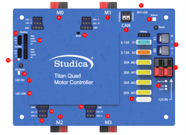
Titan: Map of Ports and Inputs
1. Power input. Input requires a 12VDC battery, and two ports are available connected in parallel. Both ports can be used for increasing the capacity or as a battery in, battery out.
2. Power output. Outputs 12VDC out to other devices such as, VMXpi or Servo Power Block.
3. Voltage indicators. There is a reverse power indicator (red) that will light up if the voltage is connected in reverse. The other two indicators display the voltage rails 5V and 3.3V.
4. Fusebox. Before voltage can be applied to the motors or power outputs (2), an appropriate fuse must be inserted into the box. Motors take 20A fuses, and power outputs take 5 - 15A fuses.
5. RGB Status Light.
6. DFU USB - used to communicate with the computer for updates and configuration.
7. CAN-BUS Input - High side (yellow) and Low side (green) inputs.
8. M1 - Motor 1 output.
9. M0 - Motor 0 output.
10. M3 - Motor 3 output.
11. M2 - Motor 2 output.
12. Boot - used only when an error occurs, and Titan cannot communicate with the computer and needs a firmware upgrade.
13. NeoPixel - addressable LED output
14. DotStar - addressable LED output
15. Pin 13/ L for LED microcontroller
16. RX/TX - LEDs for microcontroller
17. LED i2c - com port for microcontroller
18. LED USB - used to communicate with the computer for uploading code.
19. Encoder port - Quadrature encoder input
20. Limit H - High limit switch input. (Limits are pulled high and use hardware debouncing)
21. Limit L - Low limit switch input. (Limits are pulled high and use hardware debouncing)
About the Maverick DC Motor:
The Studica Robotics Maverick 12V DC Gear Motor 61:1 w/Encoder is an ideal robot motor designed for strength to endure competitions, providing a stall torque of 708 oz-in. 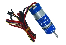
Specifications:
Function | Min | Nom | Max |
Input Voltage | - | 12VDC | - |
Gear Ratio | - | 61:1 | - |
No Load RPM | 88 | 100 | 112 |
No Load Current | - | 600mA | - |
Rated Speed | 68 | 80 | 92 |
Rated Current | - | - | 2.2A |
Rated Torque | - | 139 oz-in | - |
Stall Current | - | - | 11A |
Stall Torque | 708 oz-in | - | - |
Direction | - | CW | - |
Encoder Voltage | 4 | - | 5 |
Encoder Current | - | 6mA | - |
Encoder CPR | - | 6 | - |
Output Counts per Revolution of Output Shaft (cpr) 1,464